We used the Multimedia Logic program to represent all the logic gates. We used the program because it was much simpler than drawing it out, and it helped us visualize what it would actually look like. Each different gate had different rules that changes what the output will be.

Below are a few examples of the things we did on Multimedia Logic.

AND Identities

OR Identities
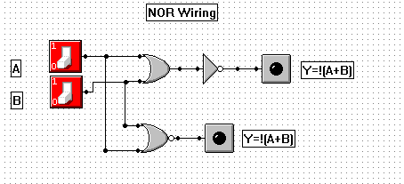
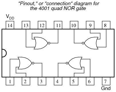
NOR Wiring
|

NOT Identities
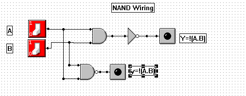
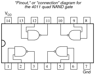
NAND Wiring
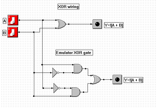
XOR Wiring
|
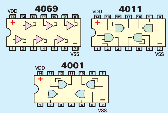
The above 3 chips are NOT, AND, and OR gates. They were used on a real life circuit board where we learned how to wire them.
|
|
The above is a XOR gate.
